CANTEACH Selected Images.......
Up
Page
1 2 3
Next Page
Click on the small images to see an enlarged view.
 |
File info: 37000-fuel/fig000_AECL_Symbol_Pick_28.jpg (size: 198 K)
Description: The figures denoted by 37000-fuel/figxxx... below form a "Historical and Pictorial Record of Canada's Power Reactor Fuel Bundle Design and Development", edited by R.D. Page and A.J. Langdon, photography by C. Baskin, CRNL. This pictorial record of Canada's power reactor fuel bundles was prepared to historically record the evolution of the power reactor fuel over the years. No one report issued over the years has been able to describe in detail the various changes that these pictures portray. It should be noted that the record does not include WR-1 type fuel or special irradiation of assemblies.
"A picture speaks a thousand words".
Source: Ron Page, email 2001.08.14 to WJG
|
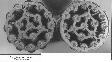 |
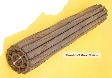
File info: 37000-fuel/fig001_3_inch_end_of_19_el_bundle.jpg (size: 122 K)
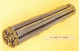
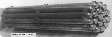
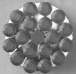
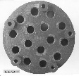
Description: This is a photo of the end-plates of the first 3 inch diameter fuel bundles. These were the first 19 element fuel bundles built in Canada and irradiated in the E-20 loop (now U-2) in the NRU reactor. They had to have a diameter of 3 inches to fit in the thick wall pressure tube installed in the E-20 loop to commission it. As the knowledge of the material properties of Zircaloy-2 was not well known at that time, the wall thickness was increased to be conservative. The bundles were assembled by screws as the method of welding the end-plates had not been developed. (circa 1959-60)
Source: Ron Page, email 2001.08.19 to WJG
|
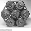 |
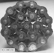
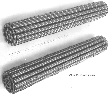
File info: 37000-fuel/fig002_NPD_7_el_Riveted.jpg (size: 152 K)
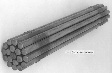
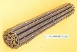
Description: This is an end view of one of the first NPD 7-element fuel bundles. They were assembled by riveting the elements to the thick end-plates. Later Tungsten-Inert-Gas (TIG) welding was used and later resistance welding to thinner end-plates, thus improving the neutron efficiency of the fuel.
Source: Ron Page, email 2001.08.19 to WJG
|
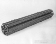 |
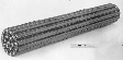
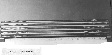
File info: 37000-fuel/fig003_NPD_7_el_Riveted_Long.jpg (size: 90 K)
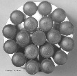
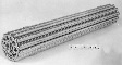
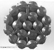
Description: This NPD 7 element riveted bundle is in its classic autoclave black.
Source: Ron Page, email 2001.08.19 to WJG
|
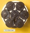 |
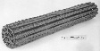
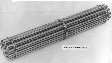
File info: 37000-fuel/fig004_NPD_7_end_welded.jpg (size: 73 K)
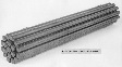
Description: This end plate on the NPD 7 is now assembled by TIG welding to a thinner end plate.
Source: Ron Page, email 2001.08.19 to WJG
|
 |
File info: 37000-fuel/fig005_NPD_7_long.jpg (size: 69 K)
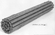
Description: In some colour photos the rusty colour on the surface of fuel bundles is from endurance testing in the lab and comes from the iron oxide from the carbon steel piping, even though the bundles rested in a Zircaloy pressure tube.
Source: Ron Page, email 2001.08.19 to WJG
|
 |
File info: 37000-fuel/fig006_NPD_19_end.jpg (size: 135 K)
Description: The end view of a NPD 19 element assembled by TIG welding.
Source: Ron Page, email 2001.08.19 to WJG
|
 |
File info: 37000-fuel/fig007_NPD_19_element.jpg (size: 82 K)
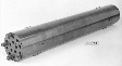
Description: The 19 elements are spaced by two wires wrapped around each elements and spot welded to the sheaths, one turn per length of element.
Source: Ron Page, email 2001.08.19 to WJG
|
 |
File info: 37000-fuel/fig008_Douglas_Point_19 el_wire_wrap.jpg (size: 85 K)
Description: The Douglas point 19 element bundles were wire wrapped but the helix around the element was doubled. Thicker wires were attached at each end to act as bearing pads so the bundles could slide through the pressure tubes with minimum wear to the tubes.
Source: Ron Page, email 2001.08.19 to WJG
|
 |
File info: 37000-fuel/fig009_DP_19_el_Colour.jpg (size: 66 K)
Description: An example of the DP 19 element bundle covered in the iron oxide and showing the extra wire pads which are partially ground to a flat surface contoured to fit the pressure tube.
Source: Ron Page, email 2001.08.19 to WJG
|
 |
File info: 37000-fuel/fig010_NPD&DP_19_Element.jpg (size: 153 K)
Description: A comparison of the NPD & DP 19 element bundles. Note that the DP bundle now assembled by resistance welded of end plates to the elements.
Source: Ron Page, email 2001.08.19 to WJG
|
 |
File info: 37000-fuel/fig011_AMF_Twisted_Tape_Brazed_19_el.jpg (size: 78 K)
Description: During the development of the wire wrapped 19 element bundles for Douglas Point, there was growing concern of the possibility of inter-element fretting of the thin .015 in. thick fuel sheaths. A study was launched to come up with different ways of spacing the elements and also to delete the end plates. The following bundles are an illustration of what were considered. The first example is the twisted tape bundle for so-called better mixing. The center element was made strong enough to take the fueling machine loads and the outer elements were recessed for the fueling machine side stops. Did not graduate.
Source: Ron Page, email 2001.08.19 to WJG
|
 |
File info: 37000-fuel/fig012_Welded_Belly_Band_AMF_bundle.jpg (size: 108 K)
Description: Another design during this period was held together by belly bands and used welded spacers. Did not graduate. AMF stands for American Machine and Foundry who was contracted to produce Uranium metal fuel for NRX and NRU Research reactors at Chalk River. They were later bought out by Canadian Westinghouse.
Source: Ron Page, email 2001.08.19 to WJG
|
 |
File info: 37000-fuel/fig013_Early_AMF_Brazed_Bundle.jpg (size: 57 K)
Description: Another design using brazing of the ferrule spacers to the elements were tried. Again did not graduate. But Zr-Be brazing was introduced.
Source: Ron Page, email 2001.08.19 to WJG
|
 |
File info: 37000-fuel/fig014_Domed_End_Cap_Brazed_AMF_Bundle.jpg (size: 89 K)
Description: To reduce the amount of Zircaloy in the end caps of the elements, thin domed end caps brazed to the sheath were tried. They had insulating pellets inside. The bundle was assembled with two planes of fixed spacers and bearing pads on the outside elements. All brazed to the sheath using both resistance heating and induction heating to melt the braze alloy.
Source: Ron Page, email 2001.08.19 to WJG
|
 |
File info: 37000-fuel/fig015_Domed_End_Cap_End_View_with_fixed_brazed spacers.jpg (size: 106 K)
Description: The end view of the above bundle with fixed brazed spacers and domed end caps.
Source: Ron Page, email 2001.08.19 to WJG
|
 |
File info: 37000-fuel/fig016_Two_Fixed_Plane_Brazed_AMF_19el_Bundle.jpg (size: 79 K)
Description: This bundle has two planes of spacers. The domed end caps have been replaced by normal solid ones to better survive the fueling machine side stop loads and remove the need of brazing the elements ends. The bearing pads were now standard.
Source: Ron Page, email 2001.08.19 to WJG
|
 |
File info: 37000-fuel/fig017_End_View_2_Fixed_Plane_Brazed_19 el.jpg (size: 92 K)
Description: The end view of the same bundle. The chamfer on the end caps was to accommodate the chamfer on the side stops.
Source: Ron Page, email 2001.08.19 to WJG
|
 |
File info: 37000-fuel/fig018_DP_Brazed_Dev_Replacement_Bundle.jpg (size: 96 K)
Description: After a number of defects during irradiation in NRU the design was abandoned and end plates were reintroduced. This bundle had no spacing and was not irradiate.
Source: Ron Page, email 2001.08.19 to WJG
|
 |
File info: 37000-fuel/fig019_DP_ Dev_small_mid_plane_Bearing_Pads.jpg (size: 87 K)
Description: The design of the replacement bundle for Douglas Point and NPD was slowly beginning to make progress. The fixed plane was dropped and replaced with a split spacer and a small pad in the center plane only. Thus the elements could now expand independently.
Source: Ron Page, email 2001.08.19 to WJG
|
 |
File info: 37000-fuel/fig020_Tube-in-Shell_Vib_Compacted_Bundle.jpg (size: 63 K)
Description: Whilst all this development was going on a radical bundle design was tried. It was called the Tube-in Shell bundle. Instead of passing the heavy water coolant over and around the fuel, it was decided to try passing the cooling water through the fuel. This bundle was filled with vibratory compacted UO2 powder, thus it had relatively low Uranium density compared to the sintered pellets. It was all brazed in assembly which was very difficult. After two defects during irradiation the design was dropped from further development. It had a major weakness with respect to heat transfer, the coolant tubes had excellent heat removal but the eccentric outer annulus was very poor.
Source: Ron Page, email 2001.08.19 to WJG
|
 |
File info: 37000-fuel/fig021_End_View_Tube-in-Shell.jpg (size: 132 K)
Description: This an end view of the Tube-in-Shell bundle. The traces of the braze alloy are evident around the tube ends.
Source: Ron Page, email 2001.08.19 to WJG
|
 |
File info: 37000-fuel/fig022_DP_Brazed_Split_Spacer_Development_Bundle.jpg (size: 74 K)
Description: The design has now matured and the spilt-spacers are now canted to prevent interlocking and a full length bearing pad has been added in the center plane. This bundle has seen endurance testing in the Sheridan Park loop and the braze alloy has a higher corrosion rate than the normal Zircaloy, thus the white appearance at the joints of the bearing pads.
Source: Ron Page, email 2001.08.19 to WJG
|
 |
File info: 37000-fuel/fig023_DP_19_el_End_View.jpg (size: 128 K)
Description: This is a Westinghouse made bundle after they took over from AMF. Note the grounding electrode marks on the end caps from resistance welding of the end plate to the elements.
Source: Ron Page, email 2001.08.19 to WJG
|
 |
File info: 37000-fuel/fig024_CGE_Development_bundles.jpg (size: 124 K)
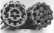
Description: These end views are of two CGE development bundles where the use of welded bearing pads and spacers were tried. Also a variant of the end plate in two pieces. Note that the inner element caps are flat. This design did not go into production.
Source: Ron Page, email 2001.08.19 to WJG
|