CANTEACH Selected Images.......
Up
Page
Previous Page
1 2 3
Next Page
Click on the small images to see an enlarged view.
 |
File info: 37000-fuel/fig025_DP_Production_Brazed_split_spacer.jpg (size: 77 K)
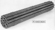
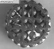
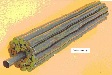
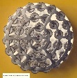
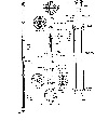
Description: The final production bundle was a brazed split spacer design with three planes of bearing pads. This design of bundle was used as replacement fuel for both Douglas Point and NPD power reactors in Canada. It was also used in Kanupp, Pakistan and Rapp I & II, India.
Source: Ron Page, email 2001.08.19 to WJG
|
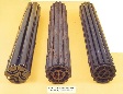 |
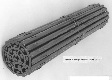
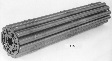
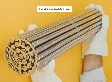
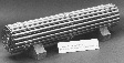
File info: 37000-fuel/fig026_NPD_7&19&DP_Brazed_Split_Spacer.jpg (size: 116 K)
Description:
Source: Ron Page, email 2001.08.19 to WJG
|
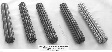 |
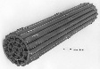
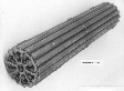
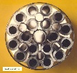
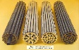
File info: 37000-fuel/fig027_NPD_7&19_DP_19_and_spilt_spacer_bundle.jpg (size: 109 K)
Description:
Source: Ron Page, email 2001.08.19 to WJG
|
 |
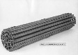
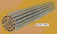
File info: 37000-fuel/fig101_Early_wire_wrap_28_el.jpg (size: 94 K)
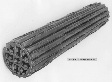
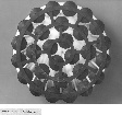
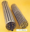
Description: During the development of the replacement D.P. design there were two other reactor fuel projects being developed. They were fuel bundles for Pickering A and Gentilly - 1 Boiling Light Water (BLW) reactors. Both these reactors were going to use 4 inch diameter pressure tubes vs the 3.25 inch of D.P. & NPD. Keeping the same size of elements as the D.P. 19 and .050 inch spacing between elements, the 28 element Pickering design was developed. CGE still preferred the wire warp rather than the toxic Beryllium braze. This wire wrap design was not favoured.
Source: Ron Page, email 2001.08.20-21 to WJG
|
 |
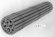
File info: 37000-fuel/fig102_End_view_28_el_wire_wrap.jpg (size: 115 K)
Description: The end plate for the 28 element Pickering bundle took many forms which are illustrated in the following photos.
Source: Ron Page, email 2001.08.20-21 to WJG
|
 |
File info: 37000-fuel/fig103_28_el_dev_bundle_Flexible_spacers.jpg (size: 96 K)
Description: CGE tried very hard to come up with a satisfactory design using only welding as the means of assembly. The angled bearing pads were welded at two points. The flexible spacer did not survive irradiation or endurance testing. The lack of redundancy in the bearing pads received a negative point in the design review. The end plate design changed again.
Source: Ron Page, email 2001.08.20-21 to WJG
|
 |
File info: 37000-fuel/fig104_28_el_welded_Dev_Bundle.jpg (size: 84 K)
Description: 28 element with welded spacers and bearing pads. Note that one of the pads welds have failed and the pad is missing. Note two piece end plate.
Source: Ron Page, email 2001.08.20-21 to WJG
|
 |
File info: 37000-fuel/fig105_28_el_dev_bundle_end_view.jpg (size: 126 K)
Description: A close up of the two piece end plate on the welded 28 element development bundle.
Source: Ron Page, email 2001.08.20-21 to WJG
|
 |
File info: 37000-fuel/fig106_CGE_28_el_straight_welded_bearing_pads_dev_bundle.jpg (size: 90 K)
Description: CGE still trying to develop the welded 28 element bundle, now with welded straight pads and more than one plane of inter-element spacers. Single piece end plate.
Source: Ron Page, email 2001.08.20-21 to WJG
|
 |
File info: 37000-fuel/fig107_28_el_Pickering_production_bundle.jpg (size: 93 K)
Description: Westinghouse came up with the final production design of the Pickering 28 element bundle. It had brazed spacers and bearing pads and a classical simple end plate design proposed by an accountant.
Source: Ron Page, email 2001.08.20-21 to WJG
|
 |
File info: 37000-fuel/fig108_CGE_28_el_brazed_pad_dev_bundle.jpg (size: 90 K)
Description: CGE was now using brazed pads and spacers and again a different end plate design. CGE traded wire wrap technology with Westinghouse for brazed technology.
Source: Ron Page, email 2001.08.20-21 to WJG
|
 |
File info: 37000-fuel/fig109_Pickering_28_inside_a_PT.jpg (size: 126 K)
Description: A closeup of the classical Pickering 28 element end plate with the bundle inside a Zr-Nb 2.5% pressure tube. Note the thickness of the pressure tube. The hoop stress on pressure vessels is directly proportional to diameter; hence the small diameter pressure tube walls can be much thinner than the thick walls required for a PWR pressure vessel. Thin Zr walls do not absorb many neutrons; hence the moderator can be placed outside the fuel area in a low pressure calandria. This is the essence of pressure tube reactor design vs. pressure vessel reactor design.
Source: Ron Page, email 2001.08.20-21 to WJG
|
 |
File info: 37000-fuel/fig110_Gentilly-1_BLW_18_el_&_CST.jpg (size: 487 K)
Description: The fuel for the Gentilly-1 was maximized by large diameter elements with a central structural tube to hold the 10 bundles in the vertical pressure tubes. The fuel worked well but, with the success of Pickering proven by the mid 70's, the 10 % (approximately) lower TUEC of BLW-type reactors was not big enough to warrant continued operation nor to justify the funding of continued development. In addition, G-1 experienced control problems (related to coolant voiding and the use of direct cycle heat transport system) and serious service water system corrosion problems. Hence, the plant was shut down and decommissioned
Source: Ron Page, email 2001.08.20-21 to WJG
|
 |
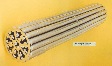
File info: 37000-fuel/fig111_Early_37_el_bundle.jpg (size: 116 K)
Description: As a backup design to the 28 element Pickering bundle, a 37 element was proposed. This was a hand built solid steel bundle with mechanical wire wrap. The 37 element was later developed for the Bruce and 600 Mwe reactors.
Source: Ron Page, email 2001.08.20-21 to WJG
|
 |
File info: 37000-fuel/fig112_Gentilly-1_BLW_18_el.jpg (size: 78 K)
Description: B&W of Gentilly -1 Boiling Light Water 18 element fuel bundle.
Source: Ron Page, email 2001.08.20-21 to WJG
|
 |
File info: 37000-fuel/fig113_Bruce_28_element.jpg (size: 95 K)
Description: Initially it was thought that the 28 element bundle would meet Bruce requirements but when the design of the reactor was uprated, it was necessary to develope the Bruce 37 element, to meet the channel power requirements. Note the staggered plane of bearing pads at end of the bundle to meet Bruce Channel requirements.
Source: Ron Page, email 2001.08.22 to WJG
|
 |
File info: 37000-fuel/fig114_Bruce_37_element_bundle.jpg (size: 321 K)
Description: The Bruce 37 element had minor differences from the other 37 elements that were developed. The end caps were squared and the bearing pads were staggered at each end of the bundle.
Source: Ron Page, email 2001.08.20-21 to WJG
|
 |
File info: 37000-fuel/fig115_End_view_Bruce_37_el.jpg (size: 116 K)
Description: The end view of the Bruce 37 element bundle. Note the grounding electrode marks of the resistance welder.
Source: Ron Page, email 2001.08.20-21 to WJG
|
 |
File info: 37000-fuel/fig116_Bruce_37_el_&_hands.jpg (size: 99 K)
Description: This photo gives a perspective of the size of the Bruce 37 element bundle relative to the man’s gloved hands. The bundles weighed approx 50 lbs and were 49.5 cm long and 10 cm in diameter.
Source: Ron Page, email 2001.08.20-21 to WJG
|
 |
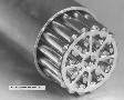
File info: 37000-fuel/fig117_End_view_Bruce_booster_rod.jpg (size: 134 K)
Description: The Bruce booster rods were designed to extend the window of the period shut before the Xenon poison prevented reactor startup. They were manufactured from enriched uranium Zircaloy alloy which was co-extruded with Zircaloy. The six 18 element bundles in an assembly was held together by ferrules and belly bands and strung together on a central structural tube. They had limited use in Bruce and were withdrawn from service.
Source: Ron Page, email 2001.08.20-21 to WJG
|
 |
File info: 37000-fuel/fig118a_Bruce_booster_&_37_el.jpg (size: 124 K)
Description: The comparative sizes of a Bruce Booster bundle and the 37 element bundle.
Source: Ron Page, email 2001.08.20-21 to WJG
|
 |
File info: 37000-fuel/fig118b_Bruce_ Booster_ rod_ Assembly.jpg (size: 563 K)
Description: This drawing of the Bruce Booster Rod Assembly demonstrates how it is assembled into a complete rod of six bundles.
Source: Ron Page, email 2001.08.20-223 to WJG
|
 |
File info: 37000-fuel/fig119_Gentilly-2_600_MWe_37_el.jpg (size: 119 K)
Description: The Gentilly 2 600 MWe reactor 37 element bundle differed from the Bruce 37 in that the end caps were conical to accommodate the fueling machine side stops and the end bearing pads were not staggered. When the Bruce 37 and the 600 MWe 37 were irradiated together, this irradiation was paid for by the Common Programme between Ontario Hydro and AECL. This programme grew into the CANDEV (CANDU Development) programme funded by the utilities and AECL. This was later formalized into the CANDU Owners Group (COG) programme of all the nuclear utilities, this supported and funded common development programmes. The 600 MWe 37 element fuel bundle is been used in the folowing reactors: Gentilly-2, Quebec; Point Lepreau, New Brunswick; Cordoba, Argentina; Cernavoda, Romania; four reactors at Wolsung, South Korea; and two in China.
Source: Ron Page, email 2001.08.20-22 to WJG
|
 |
File info: 37000-fuel/fig120_Bruce_booster_Pickering_28_Bruce&600_MWe_37_els.jpg (size: 163 K)
Description: A comparison of the Bruce booster bundle with the power reactor fuel bundles for Pickering A & B, Bruce A& B 37 element and the Gentilly-2 600 MWe reactors.
Source: Ron Page, email 2001.08.20-21 to WJG
|
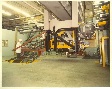 |
File info: 37000-fuel/fig121_Bruce_Fueling_Machine.jpg (size: 209 K)
Description: Bruce Fueling Machine.
Source: Ron Page, email 2001.08.20-21 to WJG
|